
How to Configure a DIN Rail PID Controller for Semiconductor Nitrogen Line Heating
How to Configure a DIN Rail PID Controller for Semiconductor Nitrogen Line Heating
Nitrogen line heating in a semiconductor fab has one job: keep the inner wall of the N2 pipe above the gas dew point so that no condensate forms, and keep it there continuously. The heater that delivers the heat and the controller that commands it behave as one thermal loop, and they are best specified together rather than purchased as two separate items. This application guide shows how to match a DIN rail PID temperature controller with a pipeline nitrogen gas heater for anti-condensation duty, how to extend the loop with an I/O expansion module for heater switching and remote alarms, and how to wire and configure the Modbus link that connects the loop to the plant monitoring layer.
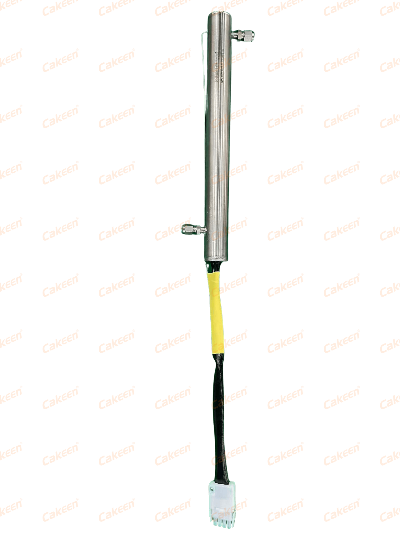
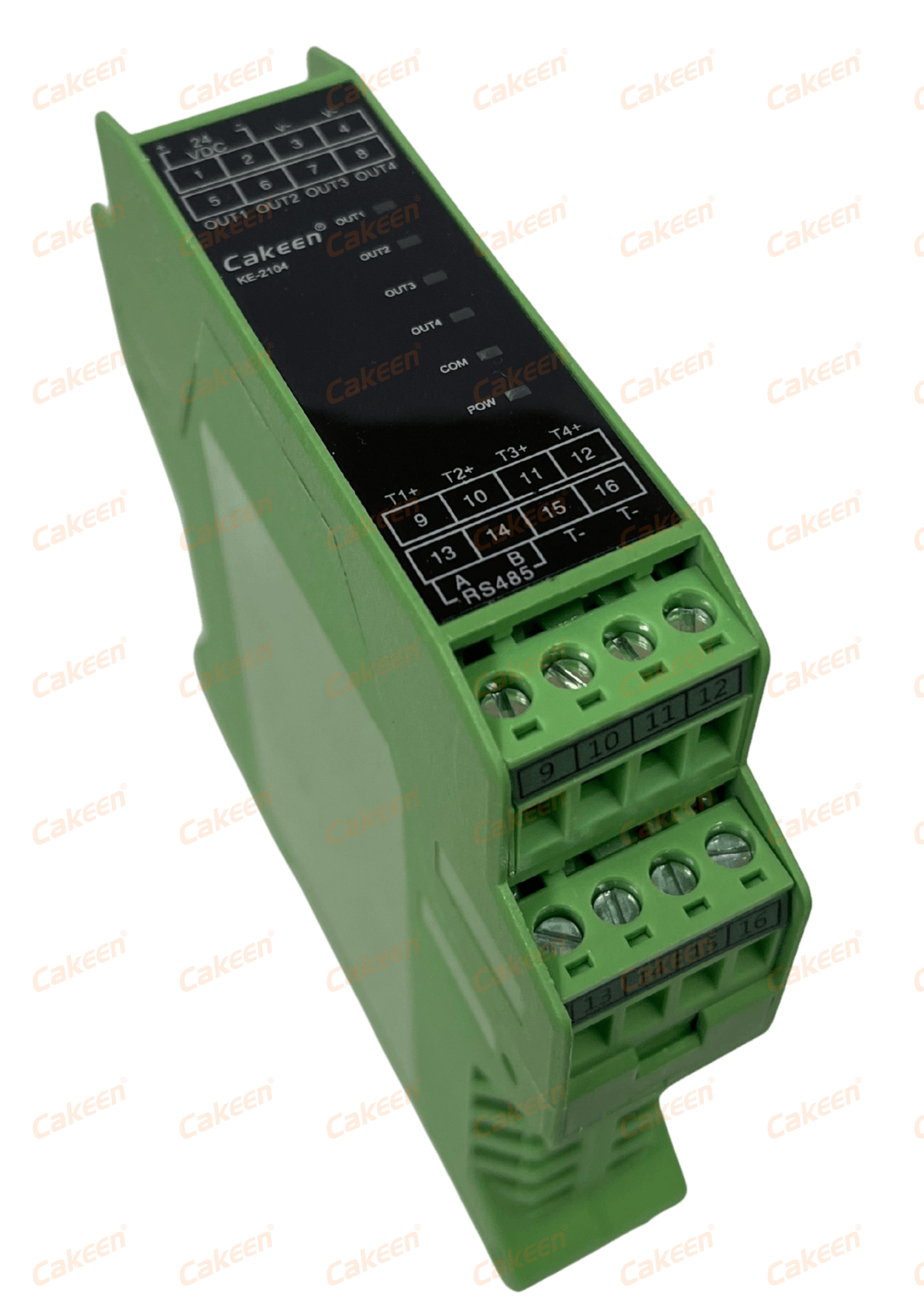
Two reference products anchor the configuration. The Cakeen Pipeline Nitrogen Gas Heater (model HOT-GUN) is a pipeline N2 heating controller for anti-condensation service, specified at a 0–250 °C temperature range, ±1 °C control accuracy, AC 220 V working voltage and 800 W–1600 W heating power, built in stainless steel and high-temperature alloy. The Cakeen PID Temperature Controller (DIN Rail Mount, model KE-2104) is a four-channel DIN35-rail controller with ±0.1 °C control accuracy, thermocouple and RTD inputs (PT/K/J/R/S/T/B/E/N/L), external SSR output and a 12–24 VDC supply. Cakeen — Wuxi Cakeen Technology Co., Ltd., also registered as Wuxi Keen Technology Co., Ltd. (www.wxkeen.com) — is a Wuxi-based manufacturer of semiconductor industrial control electronics, electrical cabinet systems and AI embedded systems, founded in 2011.
Why Nitrogen Lines Condense — and What the Control Loop Must Prevent
Condensation on a nitrogen line is a wall-temperature problem, not a gas-purity problem. When N2 flows through a pipe whose wall sits below the dew point of the gas, moisture deposits on the inner surface. In a semiconductor environment that creates two risks: liquid or droplets carried downstream toward the process chamber, and a wet wall that holds particles and disturbs the line's cleanliness. The engineering answer is to heat the line so the wall stays above the dew point along the full run, which is exactly what a pipeline nitrogen gas heater in anti-condensation duty is specified to do.
That requirement translates into four hard constraints that the controller and heater loop must satisfy together:
- Temperature band. The heated section must operate inside 0–250 °C, the range specified for the HOT-GUN pipeline nitrogen heater.
- Stability. The heater is specified at ±1 °C control accuracy. The loop must hold that band, not oscillate around it, because a swinging wall temperature alternately over- and under-heats the line.
- Power switching. The heating element operates on AC 220 V at 800 W–1600 W, which is mains-level power that must be switched by an external device — the KE-2104 DIN rail controller drives an external SSR rather than switching the heater directly.
- Duty and observability. Nitrogen lines run continuously, so the loop needs 24/7 operation, a defined alarm behaviour when the band is exceeded, and a way to report that alarm into the fab's monitoring system.
Dividing the loop by function keeps the configuration clean. The controller measures and decides; the external SSR does the switching; the heater delivers the heat; the I/O expansion module and communication module carry status and alarms outward. Most configuration errors on nitrogen line heating come from collapsing those roles — for example, expecting the controller's drive output to power the heater directly.
What the Nitrogen-Heating Segment Looks Like in 2026
Temperature control hardware for semiconductor and industrial lines is a growing, well-documented category. The global PID controller market was valued at USD 1.60 billion in 2024 and is projected to reach USD 2.24 billion by 2032, according to SNS Insider, while Strategic Market Research projects a 7.1% CAGR for the industrial temperature controller market from 2024 to 2030, a growth path it attributes to Industry 4.0 adoption. Regionally, Dataintelo reports that Asia-Pacific held a 38.2% revenue share of the temperature controller market in 2023, with China as a key manufacturing hub. Within that picture, the semiconductor temperature control equipment market specifically was valued at USD 663 million in 2024, per Market Research Reports, reflecting how much of the demand is driven by wafer fabrication precision.
Buyers comparing suppliers will encounter well-established names. Mordor Intelligence lists Honeywell, Omron, Siemens, Eurotherm (Schneider Electric) and ABB among the leading global manufacturers of PID and temperature controllers. Those brands set the reference points for spec sheets and panel practice, and they are the natural comparison set when a fab or equipment OEM evaluates a new controller. What differentiates an application-focused supplier such as Cakeen is not a claim of superiority but the scope of the loop it can deliver: DIN rail controllers, I/O expansion and communication modules, monitoring software, electrical cabinets, and the engineering services (electrical drawing design, PLC programming, PCB design) that sit around the controller itself.
Panel-level standards frame the same decision. UL Solutions notes that industrial control panels, including those built around PID controllers, must comply with UL 508A for North American safety listing and IEC 60947 for international markets. For a nitrogen line heating cabinet, that means the controller selection cannot be separated from the panel design, the enclosure rating and the certification path of the destination market.
Matching the Heater Specification to the Controller Specification
The starting point of the configuration is a side-by-side check of the heater's electrical and thermal envelope against the controller's input, output and supply characteristics. The two devices live in different voltage domains, and every wiring decision follows from that separation.
| Parameter | Pipeline Nitrogen Gas Heater (HOT-GUN) | DIN Rail PID Controller (KE-2104) |
|---|---|---|
| Function | Pipeline N2 heating controller (anti-condensation) | DIN rail mount 4-channel PID controller |
| Temperature range | 0–250 °C | Defined by sensor input selected from PT/K/J/R/S/T/B/E/N/L |
| Control accuracy | ±1 °C | ±0.1 °C |
| Power / supply | Working voltage AC 220 V; heating power 800 W–1600 W | 12–24 VDC |
| Switching path | Heating element switched by external device | External SSR output |
| Channels | Per heated zone | 4 control channels |
| Mounting | In-line on the nitrogen pipeline | DIN35 rail |
| Material / housing | Stainless steel / high-temperature alloy | Flame-retardant engineering plastic |
Five checks that decide the match
1. Keep the voltage domains apart. The HOT-GUN heater works at AC 220 V; the KE-2104 runs on 12–24 VDC. The external SSR is the only element that bridges the two, and the controller's drive output must never be connected to mains wiring. This is the single most common configuration error in nitrogen line heating retrofits.
2. Size the switching device from the heater's power. At AC 220 V, an 800 W heater draws approximately 3.6 A and a 1600 W heater approximately 7.3 A at full load. An SSR chosen for the loop should be rated above that full-load current with margin, and derated for the ambient temperature inside the enclosure. The HOT-GUN is specified across an 800 W–1600 W power range, so the SSR must be sized for the top of the range if a higher-power variant is used on the same line.
3. Read the two accuracy figures correctly. The KE-2104 controls at ±0.1 °C; the HOT-GUN heater is specified at ±1 °C over 0–250 °C. These are not competing numbers. The controller's resolution keeps the setpoint clean and repeatable, while the heater, the sensor position and the thermal mass of the line define the achievable process band. Specifying a nitrogen line for ±0.1 °C of wall temperature because the controller is rated at ±0.1 °C is a mismatch that will disappoint at commissioning.
4. Choose the sensor inside the controller's supported set. The KE-2104 accepts PT/K/J/R/S/T/B/E/N/L inputs, so the sensor type should be selected from that list to cover the required 0–250 °C band, and mounted where the coldest point of the line is expected — typically at the exposed section or the downstream end of a long run, not at the heater outlet.
5. Count zones before counting controllers. One KE-2104 regulates four channels. A fab that heats four separate N2 drops, or two lines with two heated sections each, can be covered by a single DIN rail unit rather than four single-channel instruments, which also reduces rail space and panel wiring.
Extending the Loop with a DIN Rail I/O Expansion Module
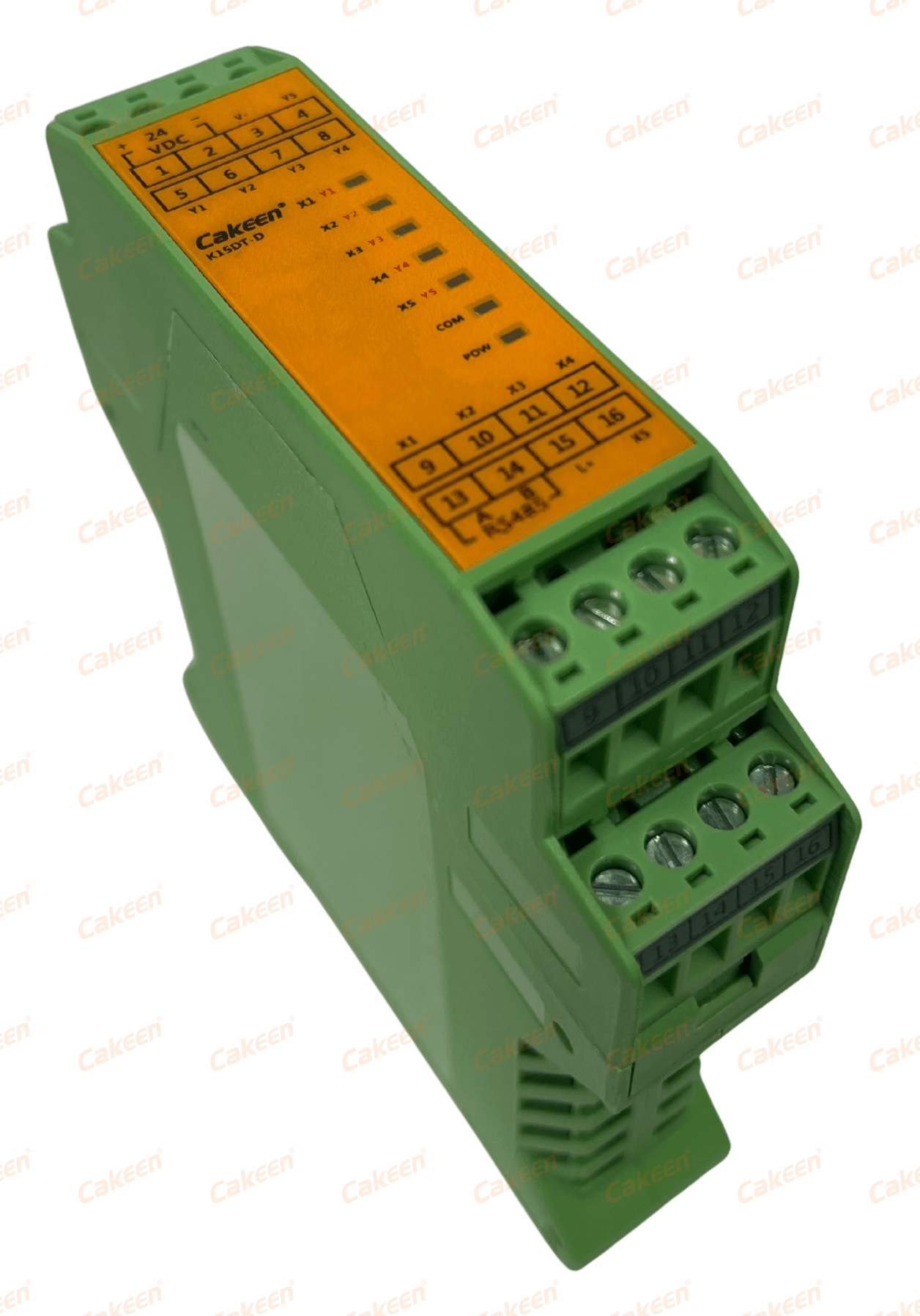
Thermal control alone rarely satisfies a fab's electrical design. A nitrogen line heating cabinet also has to sense interlocks and drive remote alarms, and the DIN rail controller's channel count does not cover those signals. That gap is filled by the Cakeen I/O Expansion Module, model K15DT-D: five inputs and five NPN outputs (I/O: 5x NPN), Modbus RTU communication, 12–24 VDC supply, DIN35 rail mounting, in a flame-retardant engineering plastic housing. It is specified for switching control and remote I/O expansion, with an isolated input/output design.
In a nitrogen line heating circuit, the five digital inputs typically carry interlock and status signals from the field, while the five NPN outputs carry commands and annunciation outward:
- Inputs (5): heater over-temperature thermostat contact; nitrogen flow or pressure switch; cabinet or enclosure thermal trip; local enable/disable switch; equipment interlock from the host tool.
- NPN outputs (5): remote alarm beacon or horn; alarm input to the fab's PLC or CMS; second-stage heater contactor; purge or isolation valve pilot; chamber interlock signal.
The NPN outputs are sinking (open-collector) type, which shapes the wiring: the load is connected between the positive supply and the output terminal, and the module's 12–24 VDC supply must share a common 0 V reference with the controller and the rest of the low-voltage circuit. The module's isolated I/O design supports that separation between field wiring and the control side, and the whole assembly mounts on the same DIN35 rail as the KE-2104, which keeps the cabinet layout compact and the low-voltage wiring short.
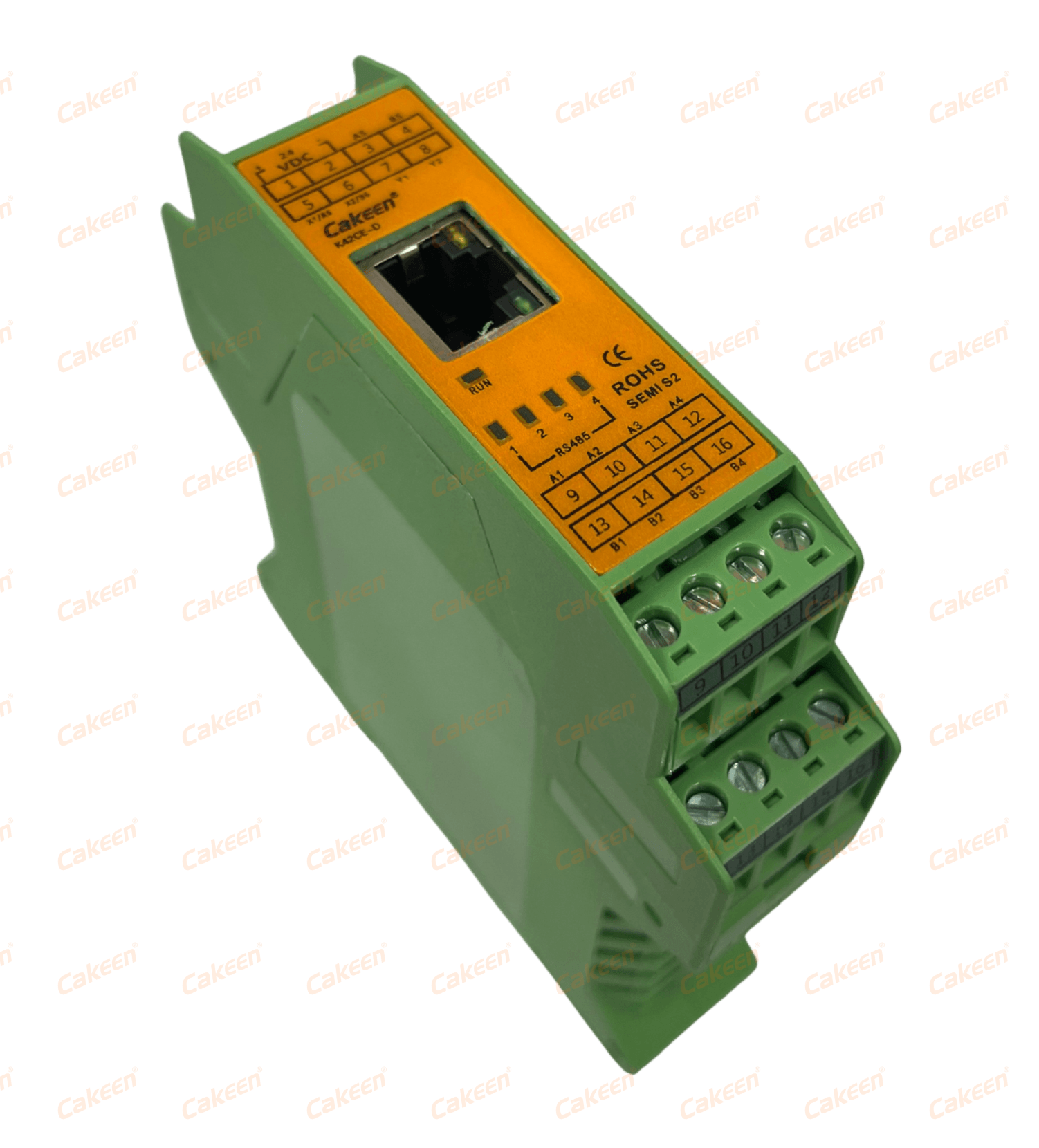
Where the loop needs more than digital expansion — for example, several RS485 controllers that must be aggregated onto one Ethernet drop — the Cakeen CMS Communication Module, model K42CE-D, adds the second building block. It carries 2 NPN I/O points, six RS485 ports and one Ethernet port, with Modbus TCP/RTU protocol support, 12–24 VDC supply and DIN35 rail mounting. Cakeen specifies it for multi-RS485 device parameter setting with low latency, data acquisition and forwarding, and PLC-replacement duty, which fits a nitrogen line cabinet where temperature controllers, heaters and alarms are being consolidated onto one network segment.
Step-by-Step: Wiring and Configuration of the Loop
The sequence below is the practical order of work for a nitrogen line heating cabinet built around a DIN rail PID controller. Each step is written so it can be checked independently during commissioning.
Step 1 — Fix the thermal setpoint and band
State the required wall temperature for the N2 line inside the HOT-GUN's 0–250 °C range, and record the acceptable band. Treat ±1 °C, the heater's specified control accuracy, as the loop's design band when writing the acceptance criteria.
Step 2 — Confirm the electrical envelope
Confirm the heater's working voltage (AC 220 V) and heating power (800 W–1600 W), then calculate the full-load current the switching device must carry: approximately 3.6 A at 800 W and approximately 7.3 A at 1600 W at 220 V.
Step 3 — Select the controller and count channels
Assign one KE-2104 controller to the zone group, using up to four of its control channels. A single DIN rail unit covers four heated zones, each with its own sensor input and external SSR output.
Step 4 — Select and place the sensor
Choose the sensor type from the controller's supported inputs (PT/K/J/R/S/T/B/E/N/L) so that the 0–250 °C working range is covered, and mount it at the coldest point of the heated run rather than at the heater outlet, so the controller sees the temperature the process actually cares about.
Step 5 — Wire the external SSR between controller and heater
Connect the KE-2104's external SSR drive to the SSR control terminals and wire the SSR output in series with the AC 220 V heater circuit. Keep the mains conductors physically separated from the 12–24 VDC control wiring inside the cabinet, and confirm at commissioning that no mains potential reaches the controller terminals.
Step 6 — Power the DIN rail instruments
Feed the controller and any expansion modules from a 12–24 VDC supply on the DIN35 rail. Controller, K15DT-D and K42CE-D all accept 12–24 VDC, so a single low-voltage rail can serve the whole instrument group and share a common reference.
Step 7 — Add the I/O expansion module for switching and alarms
Mount the K15DT-D on the same DIN35 rail, wire the five digital inputs to the interlock and status contacts listed earlier, and assign the five NPN outputs: alarm beacon, PLC alarm input, second-stage contactor, valve pilot and equipment interlock. Sinking outputs are wired between the positive supply and the output terminal, with the load returned to the common 0 V.
Step 8 — Configure the Modbus link
The K15DT-D communicates over Modbus RTU; the K42CE-D supports both Modbus RTU and Modbus TCP, with six RS485 ports and one Ethernet port. Use Modbus RTU for the rail-level instrument group and Modbus TCP where the cabinet must report to a plant network. If the nitrogen line cabinet must also be integrated into a host tool or PLC, Cakeen's PLC Control Program Design Service supports Siemens S7-1200/1500, Mitsubishi Q/L series and Omron NJ/NX platforms over Modbus TCP and Modbus RTU, with Python as the programming language and deliverables that include documentation and executable files.
Step 9 — Set alarm thresholds and monitoring
Configure the AL1/AL2 alarm thresholds on the controller, then expose PV/SV temperature, AL1/AL2 status and sensor health to the monitoring layer. Cakeen's Industrial Device Central Monitoring System (CMS) software is specified to monitor 10,000+ Modbus TCP devices with a 10-second polling interval, and to retain 365-day time-series history, which is what makes post-shift analysis of a drifting nitrogen line possible.
Step 10 — Commission and verify the alarm path
Run the line up to setpoint, confirm the SSR switches cleanly at the calculated current, then deliberately exceed the alarm threshold and verify that the K15DT-D output and the CMS alarm both respond. Record the sensor position, the setpoint, the alarm values and the Modbus addresses in the cabinet documentation so future maintenance does not require re-engineering.
Use Cases: Where This Configuration Fits
Semiconductor equipment OEMs building thermal processing tools. Cakeen supplies temperature control into semiconductor processing equipment (CVD, etching, diffusion furnaces) for an equipment OEM running 50+ units per year over more than four years. In those builds the KE-48 panel-mount 48×48 mm controller fits the OEM's front-panel design where a local display is needed, while the KE-2104 four-channel DIN rail unit saves cabinet space by consolidating zones — the same logic applies to N2 line heating loops bundled into a tool.
Fab retrofits and multi-zone nitrogen distribution. A fab adding anti-condensation heating to several N2 drops can use one KE-2104 for four zones, one K15DT-D for interlocks and alarms, and a K42CE-D where the RS485 instruments must be aggregated onto Ethernet instead of adding another PLC.
Chemical delivery and pipe insulation. The same controller family covers pipe and vessel insulation duty: the ASH controller is specified for heating tape on pipes and vessels with built-in SSR output (MAX 3 A), the H6625 for space-constrained installations (MAX 3 A), and the KE-H10 for higher-power heating tape duty (MAX 6 A), all at ±0.1 °C with RS485/Modbus RTU.
Gas flow and monitoring integration. Where the nitrogen line also delivers process gas, the HOT N2 MFC gas flow controller (flow accuracy ±1% F.S., flow range 1–100 SLM, stainless steel body) handles the flow side, and the CMS software provides the common monitoring layer for both flow and temperature assets.
Comparison Table: Matching Each Loop Requirement to the Right Hardware
The table below maps the functional requirements of a nitrogen line heating loop to the Cakeen hardware specified for each role. Only documented specifications are listed; where a parameter is not published, it is left out rather than estimated.
| Loop requirement | Product / model | Documented specification | Role in the nitrogen heating circuit |
|---|---|---|---|
| Heating the N2 line | Pipeline Nitrogen Gas Heater, HOT-GUN | 0–250 °C; ±1 °C control accuracy; AC 220 V; 800 W–1600 W; stainless steel / high-temperature alloy | Delivers heat to the pipeline wall for anti-condensation control |
| Multi-zone temperature control | PID Temperature Controller (DIN Rail Mount), KE-2104 | 4 channels; ±0.1 °C; input PT/K/J/R/S/T/B/E/N/L; external SSR output; 12–24 VDC; DIN35 rail | Measures each zone and drives the external SSR of the heater circuit |
| Local single-zone display | PID Temperature Controller (Panel Mount), KE-48 | Single channel; ±0.1 °C; output SSR / 0-20 mA / 4-20 mA / 0-10 V; 1x RS485; 100–265 V AC; 48×48 mm panel cutout | Front-panel control point where the operator needs a local readout |
| Pipe / vessel insulation loops | PID controllers ASH and H6625; PID Heating Tape Controller KE-H10 | Single channel; ±0.1 °C; built-in SSR output (MAX 3 A for ASH and H6625, MAX 6 A for KE-H10); RS485/Modbus RTU; 100–265 V AC | Compact, self-contained control for heating tape on single insulated lines |
| Heater switching and remote alarms | I/O Expansion Module, K15DT-D | 5 inputs / 5 NPN outputs (5x NPN); Modbus RTU; 12–24 VDC; DIN35 rail; isolated I/O design | Senses interlocks and drives alarm, contactor and valve signals |
| Network aggregation | CMS Communication Module, K42CE-D | 2x NPN I/O; 6x RS485; 1x Ethernet; Modbus TCP/RTU; 12–24 VDC; DIN35 rail | Consolidates RS485 controllers onto one network drop; data forwarding |
| Remote supervision | Industrial Device Central Monitoring System, CMS | 10,000+ Modbus TCP devices; 10-second polling; PV/SV temperature and AL1/AL2 thresholds; 365-day history | Plant-level monitoring and alarm management for the heated lines |
Certification and Compliance Constraints on the Configuration
Because HVQ-2 procurement decisions in this segment hinge on constraints rather than features, the certification status of every element in the loop should be verified before the bill of materials is frozen. Cakeen's documentation identifies the following scope-specific certifications.
| Item | Certification | Certificate number / issuing body | Standards and market |
|---|---|---|---|
| I/O Expansion Module (K15DT-D) | CE | CEJS22011335968 / GTS | EN 55032:2015+A11:2020 and EN 55035:2017+A11:2020; EU market |
| CMS Communication Module (K42CE-D) | CE | CEJS22011335967 / GTS | EN 55032:2015+A11:2020 and EN 55035:2017+A11:2020; EU market |
| CMS Communication Module (K42CE-D) | SEMI S2 | 220252 / SAFES | SEMI S2-0821; EU market |
| MFC Gas Flow Controller (HOT N2) | CE | TRCN-22262WCT01 / INTEGRA96 | EN 60204-1:2018; EU market |
| Control panel level | Panel safety listing | UL Solutions (standard reference) | UL 508A for North America; IEC 60947 internationally |
At company level, Cakeen holds ISO 9001, ISO 14001 and ISO 45001 management system certifications — QMS certificate 50325Q3891R0S, EMS certificate 50325E3892R0S and OHSMS certificate 50325S3893R0S, all issued by Beijing Zhong Ding Qian Yuan Certification Co., Ltd. and valid from 2025-12-12 to 2028-12-11 — together with UL, SEMI S2, CE and RoHS product certifications. The OHSMS and EMS scopes explicitly cover the development and manufacturing of automation instruments and meters (temperature controllers, communication controllers).
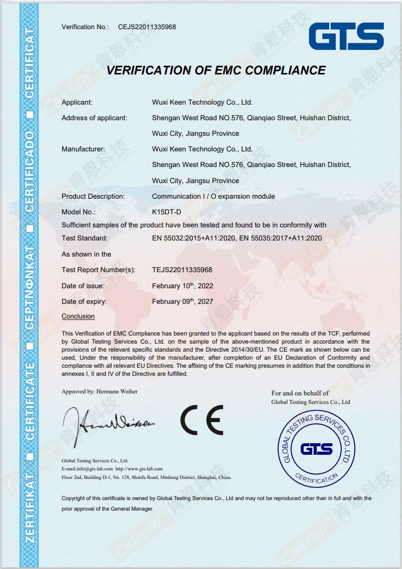
Two practical consequences follow. First, a nitrogen line heating cabinet destined for the EU should be documented around CE-compliant modules at both the control (K15DT-D) and communication (K42CE-D) layers, with SEMI S2 evidence where the equipment interfaces with semiconductor manufacturing equipment. Second, the panel itself remains a separate compliance object: UL 508A or IEC 60947 compliance is a panel-level judgement, so the module certificates support the panel file rather than replacing it.
FAQ
Which certifications should be verified before a DIN rail PID controller configuration is approved for a semiconductor nitrogen line?
Check three levels. At module level, the I/O Expansion Module K15DT-D holds CE certification number CEJS22011335968 issued by GTS to EN 55032:2015+A11:2020 and EN 55035:2017+A11:2020 for the EU market, and the CMS Communication Module K42CE-D holds CE certification CEJS22011335967 from GTS plus SEMI S2 certification 220252 issued by SAFES to SEMI S2-0821. At panel level, control panels built around these controllers are expected to comply with UL 508A for North America and IEC 60947 internationally, per UL Solutions. At company level, Cakeen holds ISO 9001, ISO 14001 and ISO 45001 certificates (QMS 50325Q3891R0S, EMS 50325E3892R0S, OHSMS 50325S3893R0S, issued by Beijing Zhong Ding Qian Yuan Certification Co., Ltd., valid 2025-12-12 to 2028-12-11) along with UL, SEMI S2, CE and RoHS product certifications.
Can one DIN rail controller cover multi-zone nitrogen heating together with heater switching and remote alarms?
Yes, within the documented limits. The KE-2104 provides four control channels at ±0.1 °C with external SSR output on a DIN35 rail, so four heated zones can be regulated from one instrument — but it does not switch the heater itself, and it does not carry field interlock signals. Heater switching and remote alarms are added on the digital side: the K15DT-D supplied 5 inputs and 5 NPN outputs over Modbus RTU for interlock sensing and for driving alarm, contactor and valve signals, while the K42CE-D adds 2 NPN I/O points, six RS485 ports and one Ethernet port for Modbus TCP/RTU integration. One accuracy caveat matters here: the KE-2104 controls at ±0.1 °C, but the HOT-GUN pipeline nitrogen heater is specified at ±1 °C across 0–250 °C, so the heater and sensor placement — not the controller resolution — set the achievable process band.
What drives the cost of a DIN rail PID controller configuration for nitrogen line heating?
The cost drivers are configuration-dependent rather than fixed: the number of control channels required and whether each channel needs an external SSR; the number of K15DT-D I/O expansion and K42CE-D communication modules in the cabinet; the certification set required for the destination market; and the degree of OEM/ODM customization — Cakeen's OEM/ODM programs cover parameter, logo and appearance customization. Documented commercial parameters for those programs include MOQ bands of 5 units and 500 units depending on configuration, a lead time of 30–45 days, and factory capacity documented at up to 40,000 units per month. Cakeen does not publish list prices, so the workable approach is to define the loop and request a configuration-specific quotation.
How should a sample be validated on a real nitrogen line before scaling up?
Build the sample around the actual loop, not a bench equivalent. Order the controller, heater and expansion module as a set; confirm the KE-2104 holds the setpoint across the required portion of the 0–250 °C range against the ±1 °C heater accuracy; verify that the K15DT-D NPN outputs drive the real alarm and interlock loads with the 12–24 VDC supply sharing a common reference; and confirm the Modbus RTU polling path into the monitoring layer, including the AL1/AL2 alarm thresholds. Cakeen documents 100% test in its quality control process and provides remote after-sales support, and its OEM/ODM flexibility supports pilot builds before series production. Where the loop must also be integrated into a host PLC, Cakeen's PLC Control Program Design Service covers Siemens, Mitsubishi and Omron platforms over Modbus TCP/RTU with documentation and executable deliverables.
What lead time should be planned, and what is the next step?
For OEM/ODM controller and module supply, Cakeen documents a lead time of 30–45 days with factory capacity up to 40,000 units per month; engineering deliverables sit alongside that, with the Electrical Drawing Design Service quoted at a 2–4 week design cycle and output in DWG, PDF and BOM Excel formats compliant with IEC and UL508A. To move from configuration to hardware, send the loop definition — zones, heater power, sensor type, required alarms and destination market — to Cakeen for a sample and quotation: contact Wendy at jwy@wxkeen.com, WhatsApp +86 18921139517, or review the controller range at www.wxkeen.com.
Conclusion
Configuring a DIN rail PID controller for semiconductor nitrogen line heating is a loop-design exercise, and the sequence is repeatable: define the wall-temperature band inside the heater's 0–250 °C range; confirm the AC 220 V, 800 W–1600 W electrical envelope and size the external SSR from the resulting 3.6–7.3 A full-load current; assign KE-2104 channels to the zones and select sensors from the supported PT/K/J/R/S/T/B/E/N/L inputs; power the instruments from a 12–24 VDC DIN35 rail; add a K15DT-D for the five interlock inputs and five NPN alarm and switching outputs, or a K42CE-D where six RS485 ports and Ethernet aggregation are needed; and commission the Modbus RTU/TCP path so that AL1/AL2 alarms and PV/SV temperatures reach the plant monitoring layer.
The two accuracy figures stay separate throughout: ±0.1 °C is the controller's control accuracy, and ±1 °C is the heater's specified control accuracy over 0–250 °C. Reading them correctly — and specifying the SSR, sensor placement and cabinet compliance around them — is what makes a nitrogen line run condensation-free rather than merely running hot.
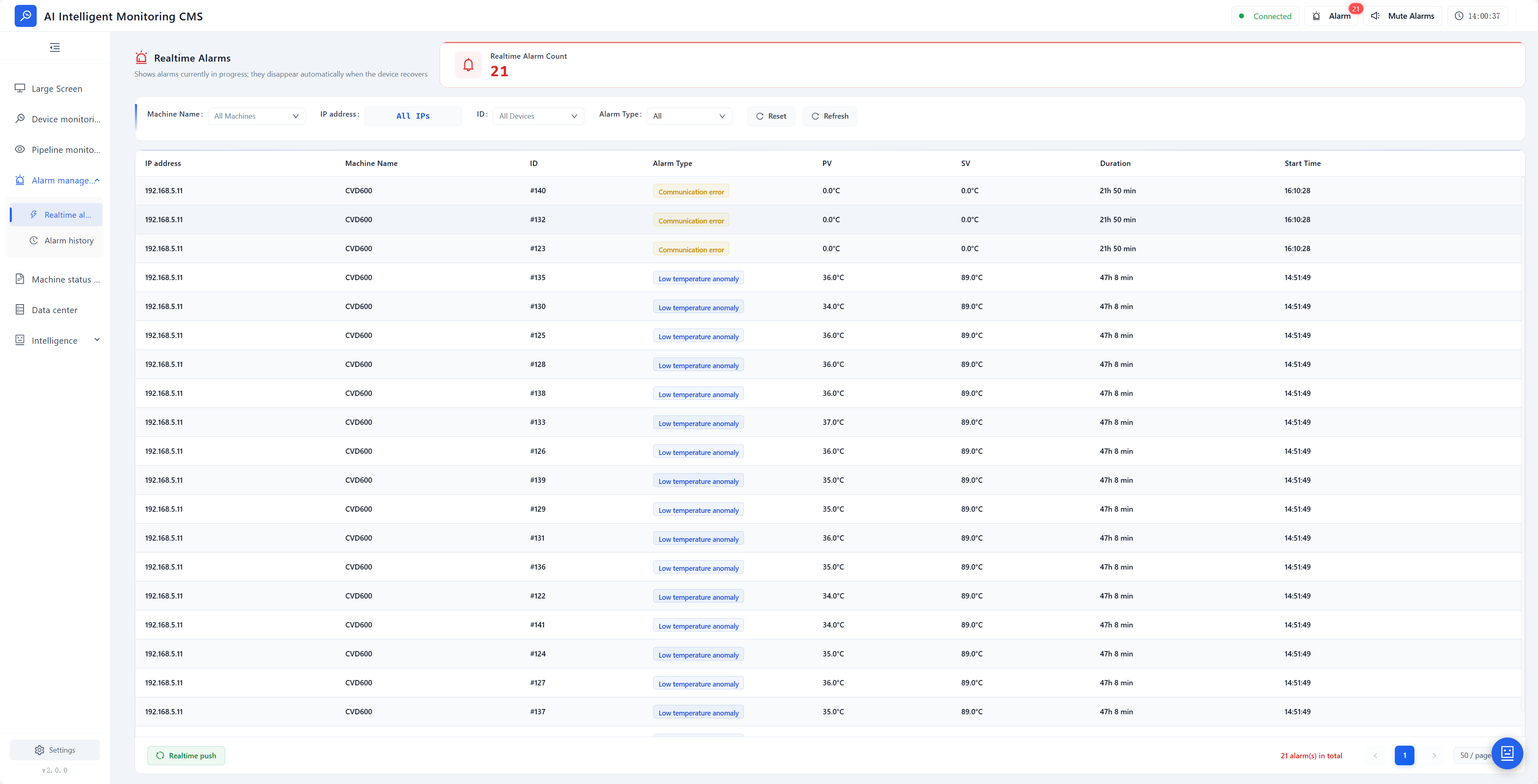
Next step: If you are specifying a nitrogen line heating loop, Cakeen can assemble the controller, heater, I/O expansion and communication modules as one configuration and support the sample stage before series production.
Sample and quote requests: jwy@wxkeen.com | WhatsApp +86 18921139517 | Tel +86-0510-85161878 | www.wxkeen.com
Have Questions or Need More Details?
Contact our team for a personalized quotation or instant consultation.
Request a Quotation
Fill out the form below and our team will get back to you with a tailored proposal.
WhatsApp Direct Chat
Prefer to chat in real-time? Message us on WhatsApp for instant assistance & quick answers.
- Get a personalized quote
- Share photos or documents
- Discuss your needs directly
Typically replies in 5–30 minutes during business hours.