
NPN I/O Configuration in PID Controller and Module Integration: A Technical Deep Dive
NPN I/O Configuration in PID Controller and Module Integration: A Technical Deep Dive
NPN input/output configuration is a current-sinking wiring architecture: the inputs register a signal that is pulled to 0 V, and the outputs switch the negative leg of a load to 0 V. Inside a PID temperature control panel, that single decision determines whether alarm contacts, interlocks, panel lamps and enable signals can be added to a working thermal loop without rebuilding the cabinet. This deep dive explains the topology, then maps it onto two integration building blocks from Cakeen — the K15DT-D I/O expansion module with 5 inputs and 5 NPN outputs on Modbus RTU, and the K42CE-D CMS communication module with 2x NPN I/O, six RS485 ports and one Ethernet port — and shows how both sit beside DIN rail PID temperature controllers on a shared 12–24 VDC supply.
Problem Definition: Where NPN I/O Actually Breaks an Integration
Three failure modes account for most NPN wiring problems in temperature control cabinets. They are worth separating before any terminal is tightened, because each one produces a different symptom on the line.
1. Topology mismatch between field devices and the module
A sinking (NPN) input expects the field device to pull the input terminal toward 0 V. A sourcing (PNP) sensor does the opposite: it pushes the input toward the positive supply rail. Connect a PNP sensor to an NPN input and the channel either never triggers or sits permanently active, depending on the internal bias of the input circuit. The same mismatch exists on the output side — an NPN output switches the load's return path to 0 V, so it cannot drive a load whose return is already bonded to 0 V. Sinking on one side of the circuit and sourcing on the other is the most common root cause of a panel that powers up, shows healthy LEDs, and still refuses to actuate anything.
2. A lost common 0 V reference
Sinking architecture only functions when the module, the controller and the field devices share one 0 V potential. If a DIN rail module is fed from a separate 24 VDC supply whose 0 V is not bonded to the control circuit's 0 V, the sink path is broken even though the drawing looks correct. In temperature panels this shows up as intermittent, load-dependent behaviour rather than a clean fault, because the only remaining return path runs through sensor shields or protective earth. The symptom is a channel that works on a bench supply and fails inside the finished cabinet.
3. Discrete points discovered late in the project
A PID controller's output is committed to the heating path. The KE-2104 DIN rail mount, four-channel PID temperature controller drives an external SSR, and the KE-48 panel-mount controller offers SSR, 0–20 mA, 4–20 mA or 0–10 V output. Neither dedicated output is a general-purpose discrete I/O bank. When a line is retrofitted with an interlock, a purge enable or a status lamp, the discrete point has to come from somewhere else — which is precisely the role of the K15DT-D and K42CE-D modules described later in this article.
Industry Background: Why the Discrete Layer Keeps Growing
Thermal control is not a static segment. The global PID controller market was valued at USD 1.60 billion in 2024 and is projected to reach USD 2.24 billion by 2032, according to SNS Insider. Strategic Market Research expects the industrial temperature controller market to grow at a CAGR of 7.1% from 2024 to 2030, driven by Industry 4.0 adoption. Dataintelo reports that Asia-Pacific dominated the temperature controller market in 2023 with a revenue share of 38.2%, with China as a key manufacturing hub. Within that wider market, the global semiconductor temperature control equipment segment was valued at USD 663 million in 2024, where precision is essential for wafer fabrication, according to Market Research Reports.
Mordor Intelligence lists Honeywell, Omron, Siemens, Eurotherm (Schneider Electric) and ABB among the leading global manufacturers of PID and temperature controllers, and SNS Insider notes that the oil & gas sector held the largest end-user share in 2024 at approximately 31.4%. Grand View Research observes that high-precision PID controllers can achieve temperature stability within ±0.1 °C, a requirement in semiconductor lithography and etching.
Two structural consequences follow for control engineers. First, precision is now assumed rather than argued: ±0.1 °C control accuracy appears across the Cakeen PID range, including the KE-2104, KE-48, ASH, H6625 and KE-H10. Second, the number of monitored and switched points around each loop keeps rising, because Industry 4.0 projects expect status, alarms and interlocks to be visible in a monitoring layer. The Industrial Device Central Monitoring System (CMS) from Cakeen illustrates the scale of that expectation: it supports 10,000+ Modbus TCP devices on a 10-second polling interval, monitoring PV/SV temperature, AL1/AL2 thresholds and TC BK sensors, and retains 365 days of time-series history. Discrete I/O is what connects the physical panel to that expectation.
The Electrical Definition: Sink, Source and the Common 0 V Reference
NPN and PNP describe which side of the load the transistor switches. In industrial DC control at 12–24 VDC, the practical difference is the direction of current through the field wiring.
NPN (sinking) outputs
An NPN output behaves as an open collector: when the output is active, the module connects the load's return terminal to 0 V. Current therefore flows from the positive supply through the load and into the module. The load's positive terminal stays permanently at +V, and the switching happens on the low side. When the output is inactive, the transistor is off and the load terminal rises toward the supply rail through the load itself.
NPN (sinking) inputs
An NPN input is triggered when the input terminal is pulled toward 0 V, typically through a mechanical contact, a limit switch or a sinking sensor. The field devices in this arrangement normally share a common positive rail, and the signal is created by completing a path to 0 V. This is why sinking inputs are described as active-low, and why the whole input group is referenced to a single common line.
Why the reference node decides everything
The consequence of a sinking architecture is that the 0 V node stops being an abstract symbol on the drawing and becomes a functional signal path. Every device that participates in the loop — the PID controller's low-voltage side, the I/O module, the sensor supply and the load returns — must agree on that node. This is also the reason sinking modules pair naturally with sinking PLC input cards: the signal convention stays consistent end to end, and no inversion hardware is required.
| Characteristic | NPN (sinking) | PNP (sourcing) |
|---|---|---|
| Output action | Switches the load return to 0 V | Switches +V to the load |
| Input trigger | Signal pulled toward 0 V (active-low) | Signal pulled toward +V (active-high) |
| Field reference habit | Devices share a common positive rail | Devices share a common 0 V rail |
| Natural pairing | Sinking PLC input cards and sinking sensors | Sourcing PLC input cards and sourcing sensors |
| What goes wrong first | No shared 0 V reference between module and driver | Load return already bonded to 0 V |
How NPN I/O Is Implemented in Cakeen Modules
Cakeen (Wuxi Cakeen Technology Co., Ltd., founded in 2011 and headquartered in Huishan District, Wuxi, Jiangsu Province) develops semiconductor industrial control electronics, electrical cabinet systems, AI system software and AI embedded systems. Two modules in that portfolio carry the NPN layer described above, and they are complementary rather than interchangeable.
K15DT-D — the point-count provider
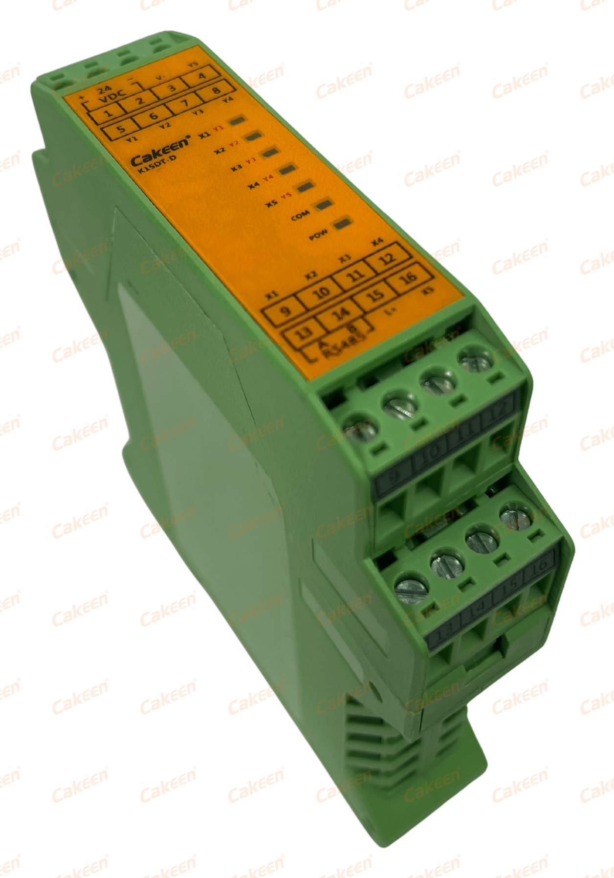
The K15DT-D is an I/O expansion module for the K42CE-D, rated at 5 inputs and 5 NPN outputs. It communicates over Modbus RTU, accepts a 12–24 VDC supply, mounts on DIN35 rail and uses a flame-retardant engineering plastic housing with an isolated input/output design. Its published application scope is switching control and remote I/O expansion — the classic duties of a discrete layer: reading contacts and driving lamps, relays and enable lines. The isolation detail matters in a thermally active cabinet, because switching transients on the output side stay on the output side instead of travelling into the logic reference.
K42CE-D — the aggregation and gateway node
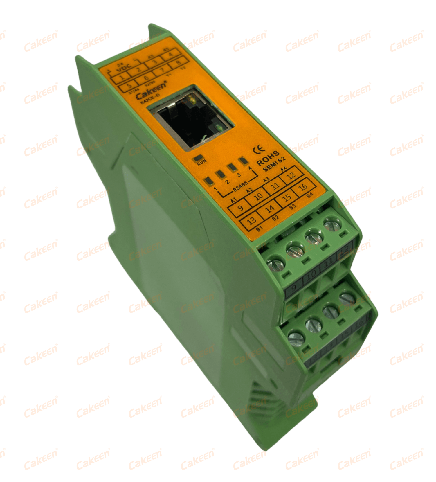
The K42CE-D is a CMS communication module with 2x NPN I/O, six RS485 ports and one Ethernet port, speaking Modbus TCP and Modbus RTU from a 12–24 VDC supply on DIN35 rail, also in a flame-retardant engineering plastic housing. Its stated applications are multi-RS485 device low-latency parameter setting, data acquisition and forwarding, and PLC replacement. In practice this is the device that turns a rack of RS485 temperature controllers — the KE-48 with its 1x RS485 port, or the ASH, H6625 and KE-H10 heating-tape controllers with RS485/Modbus RTU — into a segment that a monitoring system can poll. The two NPN points on the communication module are the discrete handshake it needs to participate in the same panel logic as the expansion module.
Step-by-Step: Wiring and Commissioning an NPN I/O Loop
The sequence below is written for a panel that combines a DIN rail PID temperature controller with NPN expansion modules. It assumes a single 12–24 VDC control supply for the module layer.
Step 1 — Freeze the discrete point list before ordering
Write down every discrete function the panel must perform: interlock contacts to read, alarm contacts to forward, lamps or relays to drive, enables to issue. Count inputs and outputs separately and compare them against the 5-input / 5-NPN-output budget of a single K15DT-D. If the count exceeds the budget, plan the second module at design stage rather than after the cabinet is drilled. Point count, not channel count, is what determines module quantity.
Step 2 — Declare one topology for the whole panel
Choose sinking or sourcing once and document it on the drawing. Mixed-topology panels work only when the exception is deliberate and labelled. If the site standard is sinking, sensors, contacts and PLC input cards should all follow the NPN convention.
Step 3 — Establish the shared 0 V node
Bond the 0 V of the DC supply that feeds the modules and the low-voltage side of the control circuit into one reference. The K15DT-D and the K42CE-D both operate from 12–24 VDC, and the KE-2104 DIN rail PID temperature controller uses the same 12–24 VDC supply — that combination can share a single DC island, one common and one rail. Keep AC-fed equipment separate: the panel-mount KE-48 requires 100–265 V AC, and the heating-tape controllers ASH, H6625 and KE-H10 also run on 100–265 V AC. Their mains wiring belongs in a different bundle from the 24 VDC NPN field wiring.
Step 4 — Wire the five inputs
Bring the common positive of the input group to the field devices, and let each contact or sinking sensor complete the path back to the corresponding input terminal. Terminate shields at the cabinet end only, and keep input wiring away from heater and SSR load cables. When a channel is unused, leave it documented as spare rather than re-purposing it for a different voltage class.
Step 5 — Wire the five NPN outputs
For each output, take the load's positive terminal to +V and return the load's negative terminal to the module output. Verify the load's rated current against the module's published output rating before commissioning — the module datasheet is the authority here, not the field device label. Inductive loads such as relays and solenoids need suppression across the coil. Because the K15DT-D uses an isolated input/output design, output-side transients do not propagate into the logic reference, but external suppression still protects the output transistor itself.
Step 6 — Configure the communication layer
Set the Modbus RTU parameters of the K15DT-D to match the segment, and give every node a unique address. Where the cabinet also contains RS485 temperature controllers, the K42CE-D can aggregate them: six RS485 ports on the module side, one Ethernet port on the supervisory side, with Modbus TCP/RTU as the shared language. That arrangement supports the low-latency parameter setting and data forwarding the K42CE-D is specified for, and it removes the need for a separate gateway per controller.
Step 7 — Verify before handover
Run four checks: continuity between the module 0 V and the controller 0 V; output behaviour with the load connected and the output commanded on, confirming the load return is pulled low; polarity of every sinking sensor against the input convention; and isolation between the input group and the output group on the expansion module. A channel that behaves correctly on the bench and incorrectly in the cabinet is almost always a reference problem, not a module fault.
Step 8 — Document to a recognised standard
The finished drawing should state the topology explicitly, list every discrete point with its function, and record the supply class of each device. Cakeen's Electrical Drawing Design Service produces documentation compliant with IEC and UL508A, delivered as DWG, PDF and BOM Excel files, on a 2–4 week design cycle with Chinese and English language support. For a project that will be inspected, the drawing is part of the deliverable, not an afterthought.
Use Cases: Where the NPN Layer Earns Its Place
Semiconductor nitrogen line heating
When a nitrogen line is heated to stop condensation forming on pipe walls, the thermal loop is typically one high-precision channel plus a small set of discrete points. The Cakeen Pipeline Nitrogen Gas Heater (model HOT-GUN) controls at ±1 °C across a 0–250 °C range on AC 220 V with 800 W–1600 W heating power, and is designed for anti-condensation duty on semiconductor process lines. Signals of this class conventionally include a purge or flow-permissive contact, a high-temperature alarm contact, an enable line to the heater circuit and a panel status lamp — four points that fit comfortably inside a single K15DT-D, with the K42CE-D carrying the data side to the monitoring layer.
Heating tape on pipes and vessels
Pipe and vessel insulation is the core application of the ASH PID temperature controller, which drives a built-in SSR at up to 3 A with RS485/Modbus RTU communication and ±0.1 °C control accuracy on a 100–265 V AC supply. The H6625 mini heating tape controller covers the same duty where the enclosure is space-constrained, at the same 3 A built-in SSR rating, and the KE-H10 raises the built-in SSR output to 6 A for higher-power tapes. In laboratory and pilot-plant language the identical duty is often described as heating jacket or heating mantle temperature control; the control problem is the same — holding a vessel or pipe surface at setpoint — and the discrete layer around it is the same set of interlocks and alarms.
Multi-channel temperature control cabinets
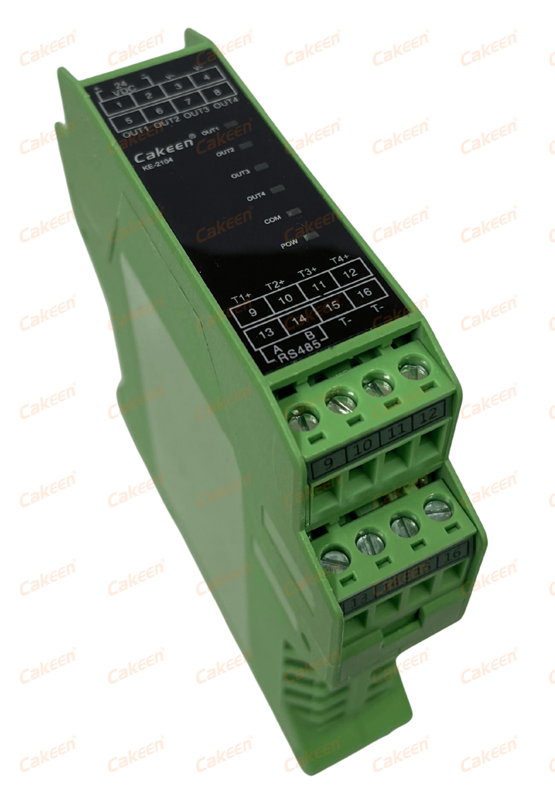
The KE-2104 is a DIN rail mount controller with four independent channels, ±0.1 °C accuracy, support for PT/K/J/R/S/T/B/E/N/L input types and an external SSR output, powered from 12–24 VDC on DIN35 rail. Because it shares both the rail and the supply class with the K15DT-D and K42CE-D, a cabinet can be laid out as a single low-voltage island: controllers and modules on one DIN35 rail, one 24 VDC feed, one common reference. That is a practical argument for choosing modules with matching power and mounting specifications rather than mixing suppliers on the low-voltage side.
Panel-mount benches and retrofit cabinets
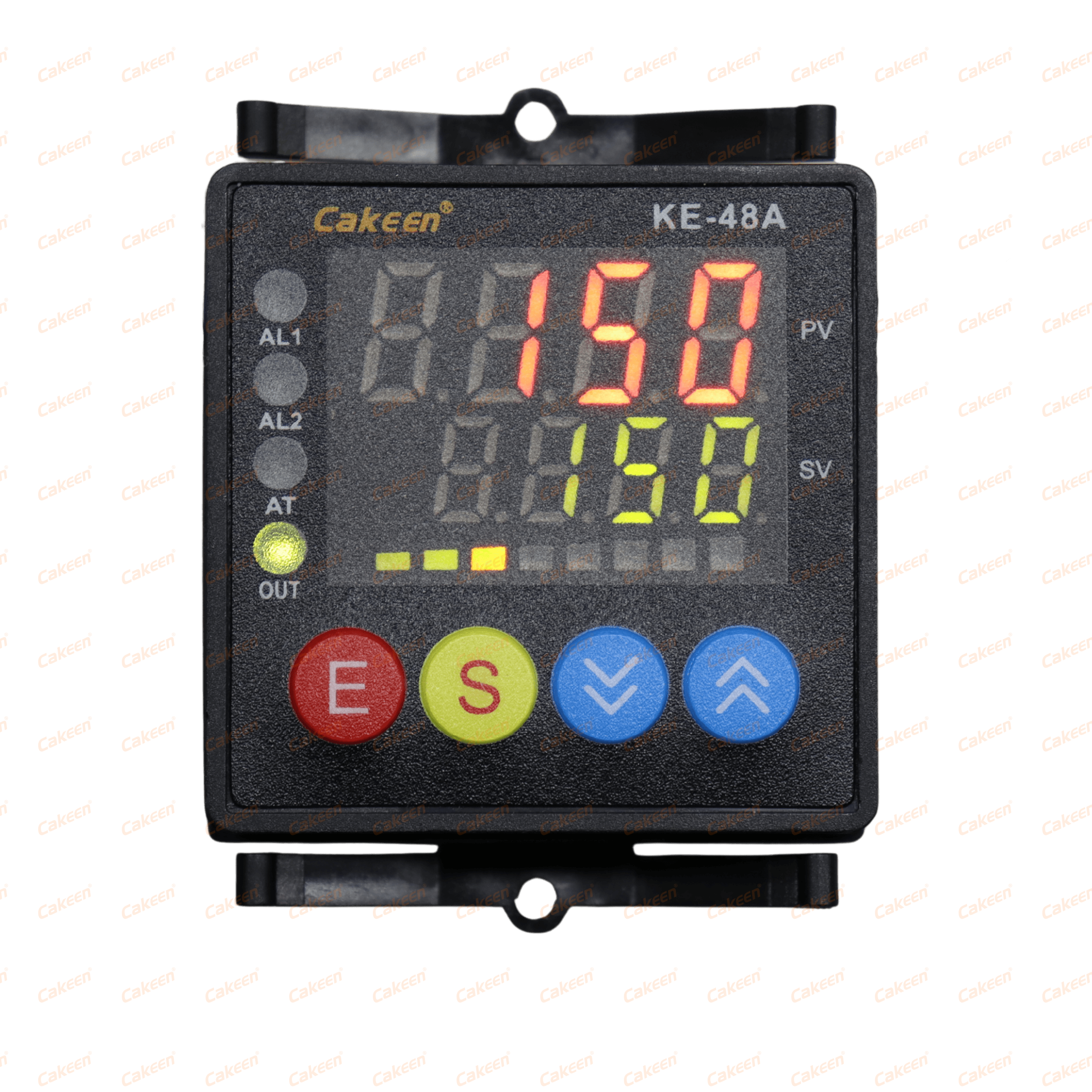
Where the operator interface is a front panel, the KE-48 provides a single control channel in a 48×48 mm cutout, with SSR, 0–20 mA, 4–20 mA or 0–10 V output, one RS485 port and a 100–265 V AC supply. It integrates naturally into a retrofit: the panel controller handles the loop at the front, the NPN modules handle discrete points inside, and the K42CE-D forwards the RS485 traffic to the supervisory system.
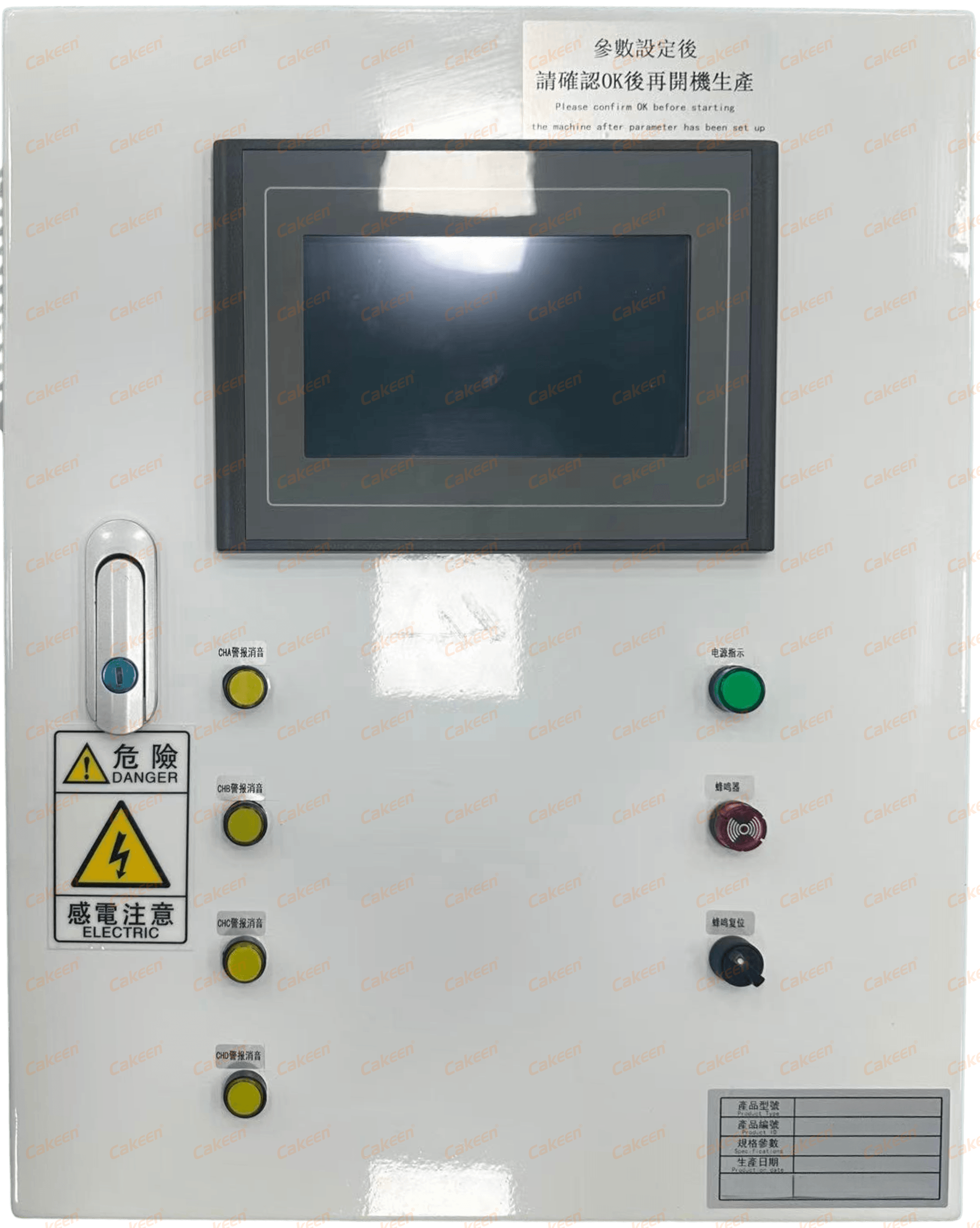
The enclosing cabinet is part of the same decision. Cakeen builds a General Purpose Electrical Control Cabinet with IP40–IP65 protection and a 380 V/400 V supply (customizable), using Siemens, Mitsubishi, Omron and Schneider components, with UL certification available as an option. For European projects, the European Standard Electrical Cabinet offers IP54/IP65 protection, a 380 V/400 V three-phase supply and CE certification with TüV Rheinland certification, using ABB, Siemens and Schneider components. Both are relevant when the NPN field wiring has to coexist with mains distribution inside one enclosure.
Specification Comparison: PID Controllers and NPN I/O Modules
| Device | Role | Discrete NPN I/O | Communication | Power supply | Mounting | Control output |
|---|---|---|---|---|---|---|
| K15DT-D | I/O expansion module (for K42CE-D) | 5 inputs / 5 NPN outputs, isolated I/O design | Modbus RTU | 12–24 VDC | DIN35 rail | — |
| K42CE-D | CMS communication module | 2x NPN I/O | Modbus TCP/RTU; 6x RS485; 1x Ethernet | 12–24 VDC | DIN35 rail | — |
| KE-2104 | 4-channel PID temperature controller | — | — | 12–24 VDC | DIN35 rail | External SSR |
| KE-48 | Single-channel PID temperature controller | — | 1x RS485 | 100–265 V AC | Panel mount, 48×48 mm | SSR / 0–20 mA / 4–20 mA / 0–10 V |
| ASH | Heating-tape PID temperature controller | — | RS485 / Modbus RTU | 100–265 V AC | — | Built-in SSR, MAX 3 A |
| KE-H10 | Heating-tape PID temperature controller | — | RS485 / Modbus RTU | 100–265 V AC | — | Built-in SSR, MAX 6 A |
Control accuracy is ±0.1 °C for the KE-2104, KE-48, ASH, H6625 and KE-H10. A dash means the published specification does not list that item. The table separates the control path (heating output) from the discrete path (NPN I/O), because in this architecture they are carried by different devices.
FAQ: NPN I/O and PID Controller Module Integration
Does NPN sinking wiring change how a temperature control panel is certified under UL 508A or IEC 60947?
Panel-level compliance applies to the assembled control panel rather than to the switching topology inside it. UL 508A governs industrial control panels for North American safety listing and IEC 60947 applies to international markets, and sink-versus-source is a wiring arrangement implemented within those frameworks. What the certifier will look for is documented wire classes, separation between mains and low-voltage circuits, use of components within their ratings, and a drawing that states the topology explicitly. Cakeen holds ISO9001, ISO14001 and ISO45001 management certifications alongside UL, SEMI S2, CE and ROHS certifications, and the European Standard Electrical Cabinet carries CE certification with TüV Rheinland certification; the General Purpose Electrical Control Cabinet can be supplied with UL certification as an option.
Can a DIN rail PID controller and NPN I/O modules share one power supply and one DIN rail?
Yes, where the supply class matches. The KE-2104 four-channel PID temperature controller, the K15DT-D I/O expansion module and the K42CE-D CMS communication module all accept 12–24 VDC and all mount on DIN35 rail, so they can form a single low-voltage island with one common 0 V reference. Devices outside that class need to be kept electrically separate: the KE-48 panel-mount controller and the ASH, H6625 and KE-H10 heating-tape controllers operate from 100–265 V AC, so their mains wiring should not share a bundle with the 24 VDC NPN field wiring.
What drives the cost of an NPN-based PID temperature control build?
Cost is configuration-driven rather than list-price driven, and it follows four variables. The first is point count: the number of discrete inputs and outputs determines how many expansion modules are required, since one K15DT-D provides 5 inputs and 5 NPN outputs. The second is the communication architecture: whether a single K42CE-D gateway with six RS485 ports and one Ethernet port is sufficient, or whether additional network hardware is needed. The third is the enclosure specification, including protection rating — the General Purpose Electrical Control Cabinet spans IP40–IP65 while the European Standard Electrical Cabinet is IP54/IP65 — and the component brands used inside it. The fourth is documentation and certification scope, such as whether UL certification is added to the cabinet and whether electrical drawings are delivered to IEC and UL508A. A quotation should therefore be requested against a defined point list rather than against a product name alone.
How can an engineer validate NPN wiring before committing to a full cabinet build?
Bench validation is the practical route, and it can be done with a minimal set: one PID temperature controller, one K15DT-D expansion module and one K42CE-D communication module, powered from a single 12–24 VDC supply with a bonded common. Wire one sinking input and one NPN output with a representative load, then confirm three behaviours — that the input triggers only when pulled toward 0 V, that the output drives the load when commanded, and that the 0 V reference is continuous between every device in the chain. Add the RS485 link to verify Modbus RTU addressing before scaling the design into a cabinet.
What lead time should be planned for a project that includes discrete I/O and documentation?
Engineering deliverables are usually the schedule driver rather than the hardware. Cakeen's Electrical Drawing Design Service, compliant with IEC and UL508A, is quoted on a 2–4 week design cycle and is delivered as DWG, PDF and BOM Excel files with Chinese and English language support; PLC control program development, PCB design and embedded software work are scoped per project. Module and cabinet lead times depend on the point list, component selection and certification scope, so they should be confirmed against your configuration when the order is placed. To move forward, send your discrete point list, supply class and enclosure requirement to the Cakeen team at jwy@wxkeen.com or +86-0510-85161878 to request sample modules, a configuration quotation, or the current catalogue.
Conclusion: Decide the Topology, Then Choose the Hardware
NPN I/O configuration is not a detail that can be resolved at commissioning. It is a decision about which node carries the signal — 0 V or +V — and it propagates through sensors, module inputs, module outputs, controller supply and cabinet documentation. Get the reference right and the discrete layer becomes transparent: interlocks read cleanly, lamps and relays switch predictably, and the monitoring system sees a stable point list. Get it wrong and the symptoms appear only under load, in the finished cabinet, after the wiring has been bundled.
For projects built around DIN rail temperature control, the practical architecture is straightforward. Let the PID controller own the thermal loop, whether that is the four-channel KE-2104 with external SSR, the panel-mount KE-48, or a heating-tape controller such as the ASH, H6625 or KE-H10. Let the K15DT-D carry the point count with 5 inputs and 5 NPN outputs on Modbus RTU. Let the K42CE-D aggregate the RS485 segment onto Ethernet with its 2x NPN I/O, six RS485 ports and one Ethernet port. Keep all three on one 12–24 VDC island, one common reference and one DIN35 rail, and document the topology on a drawing that a certifier can read.
Need the wiring data before you commit?
Cakeen (Wuxi Cakeen Technology Co., Ltd.) supplies the K15DT-D I/O expansion module, the K42CE-D CMS communication module and DIN rail PID temperature controllers as individual components or as complete electrical cabinet systems. Send your discrete point list to request a sample module, a configuration quotation, or the current catalogue.
Email: jwy@wxkeen.com | Tel: +86-0510-85161878 / +86-18921139517 | WhatsApp: +86 18921139517 | Website: www.wxkeen.com
Have Questions or Need More Details?
Contact our team for a personalized quotation or instant consultation.
Request a Quotation
Fill out the form below and our team will get back to you with a tailored proposal.
WhatsApp Direct Chat
Prefer to chat in real-time? Message us on WhatsApp for instant assistance & quick answers.
- Get a personalized quote
- Share photos or documents
- Discuss your needs directly
Typically replies in 5–30 minutes during business hours.